You can add dimensions to the 3D PMI model or 2D design geometry by measuring characteristics such as size, location, and orientation of elements. You can measure the length of a line, the distance between points, or the angle of a line relative to a horizontal or vertical orientation. Dimensions are associative to the 3D model or 2D elements to which they refer, so you can make design changes easily. Solid Edge provides a full complement of dimensioning tools so you can document your parts, assemblies, and drawings.
To learn about placing dimensions on the 3D model, see PMI dimensions and annotations.
In the Draft environment, you can add dimensions using the commands in the Dimension group on the Home tab or the Sketching tab. You also can create dimensions by retrieving them from part, sheet metal, and assembly models with the Retrieve Dimensions command.
You can use the dimensioning commands to place the following types of dimensions:
(E) Dimension groups

These dimension commands are available:
Each dimension command has a command bar that sets options for placing the dimension. When you select an existing dimension, the same command bar is displayed so you can edit the dimension characteristics.
You can place a dimension that controls the size or location of the element that it refers to. This type of dimension is known as a locked dimension. If you change the dimensional value of a locked dimension, the element updates to match the new value.
The value of an unlocked dimension is controlled by the element it refers to, or by a formula or variable you define. If the element, formula, or variable changes, the dimensional value updates.
Because both locked and unlocked dimensions are associative to the element they refer to, you can change the design more easily without having to delete and reapply elements or dimensions when you update the design.
In general, you can set or clear the lock option on the Dimension command bar or on the Dimension Value Edit dialog box to specify whether a dimension is a locked dimension or an unlocked dimension.
Note:
If the Lock button is not available, set the Maintain Relationships option in the Relate group on the Home tab or the Sketching tab.
In the Draft environment, dimensions can be placed as either locked or unlocked, depending upon the setting of the Maintain Relationships command. If Maintain Relationships is set, the dimensions are locked by default. These exceptions apply:
Dimensions placed on part views are always unlocked.
Dimensions placed between a 2D view and an element on the drawing sheet can only be unlocked.
Locked and unlocked dimensions are distinguished by color. The default colors are different in the synchronous modeling environments than they are in the Draft environment.
In the Draft environment, the color defined for each dimension type is part of the dimension style, which you can edit using the Style command on the View tab in the Style group. You can change the default color for locked and unlocked dimensions on the General page of the Modify Dimension Style dialog box.
The default color for locked dimensions—Black/White—is set by the Driving Dimension option.
The default color for unlocked dimensions—Dk Cyan—is set by the Driven Dimension option.
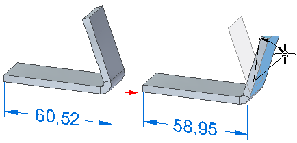
You can override the value of a driven dimension by setting its dimensional value to not-to-scale. For example, if you override the dimensional value that is 15 millimeters (A) to be 30 millimeters, the actual size of the line that you see would still be 15 millimeters (B). Solid Edge underlines the values of not-to-scale dimensions.

The Not To Scale command is available on the context menu when a dimension is selected.
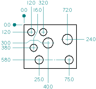
To add dimensions to elements, you can use a dimension command, such as Smart Dimension, and then select the elements you want to dimension.
As you place dimensions, the software shows a temporary, dynamic display of the dimension you are placing. This temporary display shows what the new dimension will look like if you click at the current cursor position. The dimension orientation changes depending on where you move the cursor.
For example, when you click the Distance Between command and select an origin element (A) and an element to measure to (B), the dimension dynamically adjusts its orientation depending on where you position your cursor (C) and (D).

Because you can dynamically control the orientation of a dimension during placement, you can place dimensions quickly and efficiently without having to use several commands. Each of the dimension commands uses placement dynamics that allow you to control how the dimension will look before you place it.
Note:
When the IntelliSketch Intersection option is set and you select Distance Between, you can place a driven dimension that measures to the intersection of two elements.
When placing a dimension, you can use shortcut keys to select and snap to keypoints or intersections. After you locate the line, circle, or other element that you want to snap to, you can press one of these shortcut keys to apply the point coordinates to the command in progress: M (midpoint), I (intersection point), C (center point), and E (endpoint).
To learn more, see Help topic Selecting and snapping to points.
You can drag an existing dimension so that it snaps into alignment with another dimension.
As you drag a linear dimension (A), you can locate another dimension to display a dotted alignment indicator (B). When you release the mouse button, the first dimension snaps into collinear alignment with the second.

You can use the same technique to move a radial dimension so that it snaps into concentric alignment with another radial dimension.
You can use the Line Up Text command to align dimensions by their dimension text, using alignment and justification options you select on the Line Up Text command bar. Two other options on the command bar align linear dimensions using the leader break points instead of the dimension text.
Sometimes you need to place a driving dimension to the intersection of two elements. You can do this by dimensioning to a profile point you create using the Point command.
For example, you can create a point at the theoretical intersection of two profile lines, and then use the Distance Between command with the By 2 Points placement option to dimension to the point you created. This results in a locked dimension, which you can use to control distance, size, or shape.

To learn how, see Place a driving 2D dimension to an intersection.
The Dimension Axis command sets the orientation of the dimension axis on the drawing sheet or profile plane. You can use the new dimension axis, rather than the default axis of the drawing sheet or profile plane, while you use the Distance Between or Coordinate Dimension commands. After you define the dimension axis, you can place dimensions that run parallel to or perpendicular to the dimension axis.
You can add dimensions that measure the true distance between edges in different views of the same model, such as between a principal view and a detail, cropped, or broken view.
In addition to being of the same model, the drawing views must share the same view plane. For example, you can add a dimension between an edge in a front view and an edge in a detail view with the same front orientation, but not between a front view and a side view.
You can:
Place dimensions between drawing views using any of the commands that measure distance or angle between two elements.
Select edges, center marks, bolt hole circles, centerlines, sheet metal bend lines, tube centerlines, keypoints, and hidden lines within the drawing views for dimension placement.
You can easily create and align dimensions using a grid and the Snap To Grid options on the Grid options dialog box. You can snap to a grid point or to a grid line.
While modifying an existing dimension, you can select any part of the dimension—line, text, or handle—and drag it, and it will snap into position. When you turn off the grid, you turn off the snap-to-grid feature.
There are two ways you can add dimensions automatically and generate geometric relationships to constrain the geometry:
You can use the Relationship Assistant command when editing existing profiles. This is a quick method of dimensioning and setting simple geometric relationships for any 2D information brought into Solid Edge, including information from other systems.
You can use the Auto-Dimension command when drawing new elements. The options on the Auto-Dimension page of the IntelliSketch dialog box control when the dimensions are drawn as well as whether to use dimension style mapping or not.
The Relationship Assistant command helps you finish a profile or sketch, or make it fully parametric. After applying all critical dimensions and relationships to the shape, you can use the Relationship Assistant command to apply any missing geometric or dimensional relationships to help fully constrain the model. It is a good idea to check the profile with the Show Variability option to check for degrees of freedom.
You can also use the Relationship Assistant command bar to show you how many additional relationships are required and how the shape can change based on the current relationships and dimensions.
To determine how many additional relationships are needed and how the profile or sketch can change, drag a fence around the profile, then click the Accept button on the command bar. You can then click the Show Variability button on the command bar to display the number of relationships needed. A temporary display of the profile using the highlight color is also displayed to illustrate one possibility of how the profile can change. You can click the Show Variability button repeatedly to see other variations.
If you want two or more dimensions to look the same, you can select the dimensions and apply a style with the command bar. If you want to format dimensions so that they look unique, you can select a dimension and edit formats with the command bar or the Properties command on the shortcut menu.
To learn how to format dimension terminators, see Set Terminator Size and Shape.
You can add prefix, suffix, superfix, and subfix text and supplementary information to a dimension value using the options in the Dimension Prefix dialog box. You can use this dialog box while you place or edit a dimension. To learn how, see Add and edit dimension text.
Dimensioned drawings can become cluttered and difficult to read when dimensions intersect one another. Using the Add Projection Line Break command, you can add breaks to projection lines on a selected dimension (A). The result is that break gaps (D) are inserted into the projection line (B) wherever it intersects another dimension (C). Visually, the break is represented by not drawing the projection line at the point of intersection.
(A) = selected dimension
(B) = projection line (broken)
(C) = intersecting dimensions (unbroken)
(D) = break gaps

The purpose of the projection line gap is to add visible white space and improve legibility. The size of the gap is set by the Break option on the Lines and Coordinate tab (Dimension Properties dialog box).
To add a break around dimension text that intersects other dimensions, set the Fill Text With Background Color option on the Text page (Dimension properties dialog box).
You can cut, copy, and paste a dimension with projection line break gaps as long as you select both the breaking and the broken dimensions along with the geometry.
Dimension projection lines that you have broken retain their setting during view updates, and also when you reposition the dimension text or lines for aesthetic reasons.
You can remove dimension line breaks using the Remove Projection Line Break command.
You can improve the clarity of a dimensioned drawing and avoid overlapping dimension lines by adding jogs to the dimension projection lines. This capability is supported in coordinate dimensions, linear dimensions, diameter dimensions, symmetrical diameter dimensions, and circular diameter dimensions.
You can use Alt+click to add one or more jogs:
To the dimension lines of a coordinate dimension.
To the horizontal or vertical dimension projection lines of linear, symmetrical diameter, circular diameter, and distance between dimensions.
![]()
You can remove a single jog on an existing dimension by holding the Alt key while you click a jog key point.
You can remove all jogs on a selected dimension line or projection line using the Jog button on the command bar.
You can drag the segment or the handle points created by the jog to change the length and orientation of the jog lines.
There are some limitations when adding jogs to stacked or chained dimensions. See the Help topic, dimension groups.
In the Solid Edge Draft environment, you can copy data such as prefix strings, dimension display types, and tolerance strings from one dimension to another. You also can copy the style properties associated with a dimension or annotation to another dimension or annotation using the Copy Attributes command.
You can use the mouse scroll wheel to change a driving or system dimension. As you scroll the wheel, the dimension increases or decreases in 5 percent increments. For example, if the dimension is 100 mm, the dimension will increase or decrease by 5 mm.
You can use the mouse scroll wheel to change a dimension by selecting the dimension you want to change, and then scrolling the wheel forward to increase the dimension or backward to decrease it.
An option on the General page of the Solid Edge Options dialog box controls the mouse scroll wheel function.
If the option Enable Value Changes Using the Mouse Wheel is unchecked, you can use Ctrl+mouse wheel to change a dimension value.
If the option is checked, you can use the mouse wheel to change a dimension value.
There are many instances when the dimensions of individual features in a design are related. For example, the bend radius used to manufacture a sheet metal part is usually a function of the stock thickness. You can define and automate these types of design relationships with expressions. You can select a dimension and then use the Variables command on the Tools tab to enter a formula. When the formula is solved, the dimensional value changes to the value that the formula calculates.
You might want to use dimensions with expressions for the following purposes:
Drive a dimension by another dimension; Dimension A = Dimension B
Drive a dimension by a formula; Dimension A = pi * 3.5
Drive a dimension by a formula and another dimension; Dimension A = pi * Dimension B
You can set the units of measure for a dimension by selecting the dimension and using the Properties command on the shortcut menu. You can set the units of measure for a document using the Properties→File Properties command on the Application menu.
The Show Variability option on the Relationship Assistant command bar shows how 2D elements can change based on their dimensions and relationships. Use the Relationship Assistant command to see the types of changes in a shape allowed by existing degrees of freedom.
To learn how, see the help topic, Show how a profile or sketch can change.
When a drawing view is updated in the Solid Edge Draft environment, you can track dimensions and annotations that have been changed or deleted from the model. To open the Dimension Tracker dialog box so you can identify these changes, use the Tools tab→Assistants group→Track Dimension Changes command.
On the drawing, every changed dimension and annotation is flagged by a balloon.
In the Dimension Tracker dialog box, changed items are displayed in columnar format. You can sort the changes by clicking a column heading.
You can select one or more items in the list and assign a revision name to the balloon labels on the drawing.
To learn more, see Help topic Tracking dimension and annotation changes.
When placing dimensions on sheet metal bends Solid Edge takes into account the dimension’s position relative to a bend and automatically provides the best solutions in QuickPick. The solution can dimension to one of the following:
Layer face intersection
Bend silhouette
Note:
When placing the dimension, you can press I to switch between the different dimension binding options available in QuickPick.
Editing the bend angle updates the bind style between a layer face intersection and a bend silhouette.
The bind point changes dynamically as you change the angle.