The Solid Edge application window consists of the following areas.
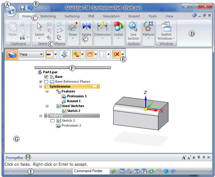
(A) Application button
Displays the Application menu, which provides access to all document level functions, such as creating, opening, saving, and managing documents.
You can use the Solid Edge Options button, located at bottom-right of the Application menu, to open the Solid Edge Options dialog box. The Solid Edge Options dialog box contains the user settings for all aspects of your session, including user profile, views, file locations, colors, and dimension styles.
(B) Quick Access toolbar
Displays frequently used commands. Use the Customize Quick Access Toolbar arrow at right to display additional resources:
![]()
Add or remove standard document-level commands.
Fully customize the Quick Access toolbar using the Customize dialog box.
Control the placement of the command ribbon. For example, you can use the Customize Quick Access Toolbar→Minimize The Ribbon command to reduce the real estate occupied by the command ribbon.
(C), (D) ribbon with commands grouped on tabs
The ribbon is the area that contains all application commands. The commands are organized into functional groups on tabs. Some tabs are available only in certain contexts.
Some command buttons contain split buttons, corner buttons, check boxes, and other controls that display submenus and palettes.
(E) command bar
A floating bar that displays command options and data entry fields for the Select Tool or any command in progress.
The command bar contains the Accept (checkmark) button that accepts the selection and the Deselects (X) button that clears the selection.
Panes (docking window)
A pane contains tab sets that group functionality according to the type of document you are working in. It also lists the contents of the active document, sorts them by name or type, and controls their visibility.
Example:
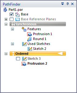
In a part document, the default pane is PathFinder, and its tab sets include the Feature Library, Layers, and Sensors. The contents of a part document may include sketches, reference planes, PMI, synchronous and ordered features, coordinate systems, and user-defined face sets.
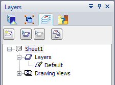
In a draft document, the default pane shown here is the Library, and its tab sets include Layers, Groups, Queries, and the Library. The contents of a draft document may include blocks, layer names, and drawing view names.
(F) PathFinder
The PathFinder can be docked or floating. The image above shows the floating option. PathFinder contains all elements in the active document. You can select elements in PathFinder and control display.
(G) graphics window
Displays the graphics associated with the 3D model document or a 2D drawing.
Command Bar 
When working in the synchronous or ordered environment, a contextual productivity tool called command bar displays in the graphics window near your cursor. Command bar provides direct access to frequently used operations based on your current selection.
(H) PromptBar
A scroll-able, movable docking window that displays prompts and messages related to a command that you select. You now can control the font size of prompt text, collapse the prompt display area, and relocate and re-size PromptBar itself.
(I) status bar
Displays messages related to the application itself.
Provides fast access to view-control commands—zoom, fit, pan, rotate, view styles, and saved views.
Houses Command Finder, a valuable tool you can use to locate a command in the user interface.