You can open jt documents in Solid Edge assembly, part, or sheet metal with the Open command. On the Open File dialog box, after you select the jt (.jt) document you want to open, click the Options button to display the Import Options for jt Documents (.jt) dialog box. The jt document will always contain facet data, but you can use the dialog box to add wire and solid data to the document.
Note:
When importing assemblies containing more than 600 to 700 part files you need to set the value of the Import DoNotSave=On parameter in the translators ini file to Off. The Import DoNotSave parameter controls whether the Solid Edge part files are created during the translation, or on the initial save of the assembly file. Setting this value to off may take longer to translate but will consume less memory.
Solid Edge supports the following jt document structures:
Monolithic—Produces a single jt document, which can contain a single part, an assembly, and assembly structure information.
Per_Part—Produces a jt document containing an assembly structure and a folder containing the jt part documents.
Full_Shatter—Produces a jt document for each node in the assembly document.
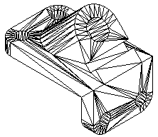
You can import facet bodies into Solid Edge Part and Assembly. A facet body is a surface representation defined by triangles.
When you import a jt facet body, it is stored in Solid Edge as a non-Parasolid body. The facet body is displayed in Feature PathFinder as a part copy. However, since the facet part copy is a non-Parasolid body, the rules are different than those for a normal part copy.
When a facet body is imported into Solid Edge Part, it is placed and treated as the base feature, but it is not considered a design body since no material can be added or removed from this type of feature.
Multiple facet bodies can exist in a part file as constructions. Only one of the facet part copies can be converted to a base feature in a document. Any other facet bodies are treated as constructions.
A document can contain both a facet part copy and design body (Brep). If a document contains both, only one can be converted to a base feature. Any other facet bodies are treated as constructions.
You cannot modify a facet part copy. If a multi-body facet jt files is imported into part, only one entry is added to the Feature PathFinder, and the multi-body facet is treated as a single entity.
A facet body from a jt files can be added to a Solid Edge document with either the Insert Part Copy command or the File Open command.
You cannot locate faces, edges, or vertices of a faceted body. You can only locate the entire body.
Commands that require faces, edges, or vertices as input will simply fail when trying to locate the faces, vertices or edges of a faceted body. For example, when drawing a sketch, the Sketch command will not locate faces, edge, and vertices of a faceted body. When the Solid Edge part file contains a facet body, any commands that only add or removes material from the base feature are disabled.
Commands that calculate physical properties are supported for facet bodies in a Solid Edge part document.
You can check for interference between facet bodies in a Solid Edge assembly document.
Faceted bodies are represented in Feature PathFinder with a unique icon and name. The color of the facet body is inherited from the sending system. You can control the display mode of the facet body in Solid Edge, as with any other design bodies. However, when the body is shaded, the edge display is never enabled. You can use the shortcut menu in either Feature PathFinder or the graphics window to show or hide the facet body.
Teamcenter captures JT content in a dataset called DirectModel. The relation that connects a DirectModel Dataset to an Item Revision is IMAN_Rendering.
BOM synchronization is controlled by the Teamcenter preference SEEC_BOM_Synchronization. SEEC Administrator delivers this preference with BOM Synchronization off. To enable BOM synchronization, set the SEEC_BOM_Synchronization preference to true.
The Teamcenter preference SEEC_Foreign_Datasets determines what datasets to consider when a Solid Edge 3D dataset is not saved to the Item Revision. Preference syntax details are available in the Solid Edge Embedded Client Administrator's Guide.
For more information, see the Multi-CAD in the Teamcenter managed environment help topic.
You can save Solid Edge assembly, part, and sheet metal documents in .jt format with the Save As command. On the Save As dialog box, after you select the Solid Edge document you want to save, click the Options button to display the Solid Edge to JT Translation Options dialog box. You can use the dialog box to control how the Solid Edge document is saved in .jt format.
The SePvTrn.ini file, found in the Solid Edge Program folder, is used to store the settings selected from the user interface. When you change a parameter in the options form, a new value is saved to the SePvTrn.ini file.
Note:
When you are working in a Teamcenter-managed environment through Solid Edge Embedded Client, the file SEECtoJT.ini is used to store settings selected for the user interface. The SEECtoJT.ini file is found in the Solid Edge Program folder.
Some parameters are not exposed through the user interface. You can use a text editor, such as Notepad, to set these parameters. However, if you edit this file, use extreme caution in setting these parameters. Errors in this file can adversely affect translation quality.
|
Parameter in SePvTrn.ini file |
Description |
|---|---|
|
Enable Logging = 0 |
Turns on or off the creation of the log file. The default is off. |
|
Include Precise Geometry = 0 |
Controls the inclusion of B-REP definition in resultant jt files. jt file size will be larger when set to true, but jt viewer functionality that is able to use the precise B-REP definition will provide more accurate results. The value can be a boolean value (1 or 0). |
|
JT Units = m |
Controls the model units for the jt files. Possible values include:
|
|
ChordalOption = RELATIVE |
Controls the interpretation of the Chordal LOD parameter.
Possible values include a string equal to:
|
|
StructureOption = PER_PART |
Controls the mapping of the jt product structure to the jt file structure for any jt output. Possible values include:
|
|
WriteWhichFiles = ALL |
Controls the filtering of the jt files to be written based on the content. Possible values include:
Possible values include:
|
|
PmiOption = NONE |
Not used |
|
partMonitor=false |
|
|
Compression = true |
Controls the toolkit's ability to output compressed jt files. Setting the value to false writes uncompressed jt file. Setting it to true writes compressed jt files. Possible values are a boolean value of true or false. |
|
TristripOpt = true |
Controls the toolkit's ability to perform an additional optimization. The additional optimization increases the visualization performance of renderable geometry data in each jt part file. When set to true, the toolkit attempts to reduce the number of triangles to render without reducing the quality of the geometry displayed. This increases visualization performance, but may increase the jt file export time. When used in conjunction with the compression option, this option may increase jt part file sizes due to alterations in the renderable geometry's data composition. The value can be a boolean value of true or false. |
|
SeamSewing = true |
Controls the toolkit's logic to create shared edges between adjacent surfaces in the renderable geometry. This helps to eliminate gaps in the geometry. This option is paramaterized by the seamSewingTol option. The value can be a boolean value of true or false. |
|
SeamSewingTol = 0.001 |
Controls the tolerance used by the SeamSewing option to compare two vertices for equality in a seam to be sewn. The value specified represents a floating point fractional percentage of the bounding box diagonal of the part undergoing seam sewing. The option can be a floating point value in the range [0.0,1.0]. |
|
BrepPrecision = DOUBLE |
Controls the floating-point precision for any B-REP geometry data saved in a jt file. Possible values include:
This parameter controls how the data is stored on the disk and does not affect the settings of the Include Precise Geometry or XTBasedNewFormat parameters. Possible values include:
|
|
AutoNameSanitize = true |
Controls the toolkit logic to remove undesirable characters m the names of jt files by replacing them with an underscore character (_). The default set of undesirable characters that will be replaced is: $ ~ ` ! @ # % ^ & * ( )- + = " ' ; , . < > ? [ ]{ } You can use the FilenameSanitizeSet, FilenameSanitizeSetAdd, and FilenameSanitizeSetDelete options to modify this set of characters. The value can be a boolean value (true or false). |
|
deleteUnusedparts=true |
|
|
WriteAsciiAssembly = false |
Controls the toolkit logic preventing the use of the jttoascii utility on resultant assembly-only jt files. When set to true, the translator creates an .A jt file equivalent for each .jt file that is created. In order for this option to function, jt Utilities product must be configured so that the jttoascii executable can be run from the same command line environment as the toolkit client application. The value can be a boolean value (true or false). |
|
AutoLowLODgeneration = true |
Controls the toolkit logic that analyzes and potentially creates two default lowest LODs. Specifically, this logic (potentially) creates a convex hull ("shrink wrapped") and bounding box representation of a part's geometry. The value can be a boolean value (true or false). |
|
SmartLODgeneration = false |
Controls the toolkit logic that automatically analyzes and creates LODs to smooth the transition between the lowest user-defined LOD and the highest LOD generated by the autoLowLODgeneration option. This option may result in an arbitrary number of additional LODs. The value can be a boolean value (true or false). |
|
Number of LODs = 3 |
Contols the number of LOD definitions. The value must be an integer greater than 1. |
|
AdvacedCompressionOn = false |
Controls the toolkit's ability to output jt files using advanced or standard compression. This option is used in conjunction with the compression option. Setting this option to false enables standard compression of the jt files. Setting it to true enables advanced compression of the jt files. Possible values are a boolean value of true or false. |
|
AdvacedCompressionLevel (global)= 0 |
Controls the level of compression. The compression level can be set from 0 (minimum compression) to 1 (maximum compression). As the compression value increases, the compression increases and the amount of data kept is decreased. Minimum compression maintains precision for the translated geometry information, but produces a larger file size. Maximum compression results in loss of precision to achieve a smaller file size. The value can be a floating point value in the range [0.0,1.0]. |
|
XTBasedNewFormat = true |
Controls the inclusion of XT Brep into the jt files. When this is true: Solid Edge uses the Parasolid Brep by adding it to the jt files. Prior to version 15 Solid Edge translated the jt file from Parasolid to jt Brep format. Reusing the Parasolid Brep is much faster. Solid Edge uses the Solid Edge triangles instead of creating them from the jt Brep. When X_TBasedNewFormat is enabled the Levels Of Detail (LODs) are not used since Solid Edge uses the Solid Edge triangles instead of generating them. |
|
IncludeVisibleConstructions = true |
Controls the inclusion of Solid Edge construction geometry in the jt files. If this is true, all visible constructions are translated to jt format. |
|
IncludeSEProperties = true |
Controls the inclusion of Solid Edge properties in the jt files. |
|
ApplySimplifiedTopAsmOverride=false |
Applies the Simplified override at Top assembly during translation if there is a simplified data available in Solid Edge top assembly file. Possible values are a boolean value of true or false. |
|
ApplySimplifiedSubAsmOverride=false |
Applies the Simplified override at subassembly level during translation if there is a simplified data available in Solid Edge sub-assembly files. Possible values are a boolean value of true or false. |
|
ApplySimplifiedPartOverride=false |
Applies the Simplified override at part level during translation if there is a simplified data available in Solid Edge part files. Possible values are a boolean value of true or false. |
|
Export Inter-Part Copies as constructions=true |
Export inter-part copies as construction surfaces. Possible values are a boolean value of true or false. |
|
UpdateChangedPartOnly=false |
Prevents an overwrite of jt files whose content is not changing. When set to true, the bill of materials for each jt file to be written is compared to that of any potentially overwritten jt file. If the product structure content or versions of this content differ, the jt file will be overwritten. Otherwise, the jt file will not be overwritten. This is for incremental jt translation support. Possible values are a boolean value of true or false. |
|
SEPartFileAsSingleJTFile=true |
Exports a single jt file for SE Part document. If this flag is set to true, Save As jt on SE Part document outputs a single jt file. Possible values are a boolean value of true or false. |
|
Import Multiple Bodies As Single Part file=On |
This parameter is used during the import of precise assembly geometry. When multiple solid bodies are encountered in a single part definition this parameter specifies how the bodies are added to the assembly file. If the parameter is set to the default value,On, a part file containing multiple construction bodies is created and added to the assembly. If the parameter is set to Off, an individual part file is created for each body contained in the part definition. A subassembly is then created, to which the individual part files are added. |
|
Import DoNotSave=On |
This parameter controls whether or not the Solid Edge part files are created on import, or on the initial save of the assembly file. For small to intermediate file sizes this enhancement works well. For assemblies that are larger than 600-700 part files you need to disable this parameter to insure there is sufficient memory to create the files on save. |
|
HealAndSew=0 |
Controls whether to heal and sew free surfaces to create a solid body. When given a set of sheet bodies the software cleans the input sheets of self intersections and loop inconsistencies. It then identifies and removes very small surfaces or sliver sheets from the set of sheets. Edges of adjacent surfaces are then used to fill holes where slivers were removed. Larger holes from missing surfaces are also filled. After the healing process is complete a single stitch operation at 1.0e-5 (meters) is attempted to create a solid body. The value can be a boolean value (1 or 0). |
|
ImportSewSheet=1 |
Controls whether all surfaces and sheet bodies are to be stitched to a tolerance of 1.00e005 meters. It may be to your advantage not to stitch the surfaces on import, but to evaluate what needs to be stitched and perform the stitch after you import the file. This option is on by default. If the stitching operation creates a valid volume, the volume is converted to a solid. The value can be a boolean value (1 or 0). |
|
ImportBooleanSolid=1 |
Controls whether to boolean all solid bodies together and insert the results into PathFinder as part copies. This option is off by default. If the option is off, all solid bodies are added as individual part copies to PathFinder. The value can be a boolean value (1 or 0). |
|
CreateAssociativePartsInAssembly=0 |
During the import of a jt assembly this parameter determines whether if associative link to the jt file is created. By default the creation of the associative links are disabled. |
|
ImportSheet=1 |
If the jt file contains precise sheet (surface) data it is imported or excluded. By default this is enabled (1) |
|
ImportWires=1 |
If the jt file contains precise Wire (curve) data it is imported or excluded. By default this is enabled (1) |
|
Import Triangles Only=0 |
Controls whether the faceted data or Brep data is imported from the .jt file. A false, “0” value retrieves the Brep body, while a true, “1” value retrieves triangle data without the Brep data. The value can be a boolean value (1 or 0). |
|
ImportImprintCurve=1 |
Controls whether to combine all curve data into a single part copy. It may be to your advantage to identify the curves that you do not need and either hide or delete them before importing the file. This option is on by default. The value can be a boolean value (1 or 0). |
|
MakeBaseFeature=1 |
Controls whether to make the imported solid body the base feature for the Solid Edge model. If there is more than one solid body in the Parasolid (.X_T) file, no base feature is created. In this case you can use the Make Base Feature command to select a solid to use as the base feature or construct a new base feature for the model. If you clear this option, all solid bodies contained in the Solid Works file you are importing are placed in PathFinder as a part copy rather than a body feature. Inserting bodies as a part copy requires you to select or create a base feature. The value can be a boolean value (1 or 0). |
|
ImportCheckBody=0 |
Controls whether to perform a full body check on the file. The value can be a boolean value (1 or 0). |
|
Stitch=1 |
Specifies if the Heal and stitch option, the Stitch Option, or neither option is used when opening the file. Setting the value to 1 enables the dialog and will either heal and stitch, or stitch surfaces depending on the radial button setting. Setting the value to 0 will not heal and stitch nor will it stitch surfaces when disabled. |
|
EnableDefaultOutputPath=1 |
Controls whether the output folder is the same as the input folder for the documents you are importing. If you select this option and import an assembly, the assembly and the individual parts in the assembly are imported to the same folder. The value can be a boolean value (1 or 0). |
|
ImportOutputPath= |
Specifies the path to which the files will be output. |
|
[LOD 1] |
A grouping of parameters that controls tessellation and simplification for a specific LOD. The value can be in the range of [1–n], where n is specified by the Number of LODs parameter. |
|
Chordal |
Specifies the maximum distance that a (tessellated) line segment may deviate from the actual curve it is approximating. The value specified is interpreted as dictated by the chordalOption option. For best results, use chordal values in conjunction with the Angular parameter. Chordal values affect primarily the larger features of the model, while angular values affect primarily the smaller features. The value can be a floating point in the range [0.0,1.0] for relative interpretation, arbitrary range for absolute interpretation. |
|
Angular |
Specifies the maximum angle (in degrees) between two adjacent (tessellated) line segments in a curve approximation. For best results, use angular values in conjunction with the Chordal parameter. Angular values affect primarily the smaller features of the model, while chordal values affect primarily the larger features. The value can be a floating point value in the range [0.0,90.0]. |
|
Length |
Specifies the maximum absolute length of (tessellated) line segments in a curve approximation. The value can be a floating point value of arbitrary range, depending on the magnitude of modelling units used for geometry. |
|
FeatureSuppression |
Specifies the size tolerance of holes and arcs to suppress. The value specified represents a floating point fractional percentage of the bounding box diagonal of the part undergoing suppression. A value of 0.0 indicates no suppression. The value can be a floating point value in the range [0.0,1.0]. |
|
Simplify |
Specifies the minimum percent reduction of renderable geometry (triangles) for the specific LOD versus the highest LOD. The value specified represents a floating point fractional percentage of the number of triangles in the highest LOD. This value should be left at 1.0 (100%) for the high LOD. The value can be a floating point value in the range [0.0,1.0]. |
|
Export 3D Bodies |
Specifies which body is included in the .jt file. Possible values include:
|
|
Export PMI |
Controls whether PMI is exported to the .jt file. Possible values are true or false. |
|
Export Coordinate System |
Controls whether coordinate systems are exported to the .jt file. Possible values are true or false. |
Note:
If you want to save documents to .jt format while working in Insight, you should set structureOption=MONOLITHIC.
You can use the Export 3D Bodies parameter in the SePvTrn.ini file to specify how to save a sheet metal file to .jt format. By default, the parameter is set to 0, which includes only the design body in the .jt file. You can set the parameter to 1 to include only the flat body in the .jt file or to 3 to include all bodies in the .jt format.
Note:
If you set the parameter to 1 and there is no flat body for the sheet metal part, the .jt file includes the design body instead.
You can use the Save PMI Data option on the Solid Edge to JT Translation Options dialog box to save all product manufacturing information (PMI) data and all model views to the JT file being created. When you select this option other JT save options are disabled and the appropriate options are set to support PMI data. Precise geometry is always sent when the Save PMI Data option is selected even if the Include Precise Geometry option is not set.
You can use the Save Coordinate System option on the Solid Edge to JT Translation Options dialog box to save the coordinate system to the JT file being created.
Documents saved in jt format contain attributes that describe the information contained in the document. These attributes are the equivalent of file properties used by Solid Edge to describe document information.
When you export a Solid Edge document to jt format , Solid Edge file properties are written where they can be read by viewers, and other CAD systems that read jt format.
When you import a jt to Solid Edge all jt user attributes are imported and saved as file properties. There is no file property associativity between the Solid Edge document and the jt document. In other words, if you change attribute values in the jt file, the changes are not updated in the Solid Edge file. There is no user interface to control the import of file properties. You can use the ImportjtProperties parameter in the SePvTrn.ini file. Setting the parameter to True enables the import of jt attributes to Solid Edge file properties. By default, the value is True. If the parameter does not exist in the SePvTrn.ini file, the default value of True is assumed and the attributes are imported.
The [Import Property map] section of the SePvTrn.ini file serves as a mapping table, allowing you to map jt attributes to Solid Edge file properties. The mapping table contains two columns. The left column is an exact match of the Solid Edge property page string and the right column is the string found in the jt file. [Import Property map]
Document Number = I-DEAS Part Number
Author = Creator Project Name = I-DEAS Project
Density = CAD_Density
Note:
Parameters found in the [Import Property Map] section are case insensitive.
Physical properties are exported by IDEAS and NX with the same naming conventions. This provides a standard name used by the VIS viewers to display or calculate properties of a solid body. Solid Edge exports physical properties using the same naming convention.
Use SePvAdp.exe, found in the Solid Edge Program folder to translate Solid Edge files through a standalone interface. The executable uses the SePvTrn.ini file to control the jt output translation settings. Any changes to the .ini file must be done prior to invoking the translator.
To run the executable, Solid Edge must be installed on the computer and SePvAdp.exe must exist in the Solid Edge Program folder. The executable does not launch a full version of Solid Edge, so it requires less memory, leaving more resources available for processing larger files. When you select the files for translation, any folder or file names containing spaces must be enclosed in quotation marks “ “.
Once started, the only indication that the translator is running is the presence of SePvAdp.exe on the Processes tab in Task Manager. Once the translation of all selected files is complete, the process ends and is no longer displayed in Task Manager. Subsequent exportation of the same input file to the same output folder will overwrite the existing jt file.
You can invoke the executable through Start→Run in Windows Explorer or through a command line prompt in a DOS window. Examples of the command line prompt include:
C:>”C:\Program Files\Solid Edge v#\Program\SePvAdp.exe” <input_filename>
C:>”C:\Program Files\Solid Edge v#\Program\SePvAdp.exe” <input_filename_1> <input_filename_2> and so forth.
C:>”C:\Program Files\Solid Edge v#\Program\SePvAdp.exe” -g -o <output_folder> <input_filename>
C:>”C:\Program Files\Solid Edge v#\Program\SePvAdp.exe” -g -o <output_folder> <input_filename_1> <input_filename_2> and so forth.