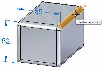
In a synchronous part model, intersection points are derived from model edges, cylindrical or conical face axes, and rounds.
Choose a dimensioning command, such as Distance Between or Smart Dimension.
Place the cursor on the edge, round, blend, or blend patch where you want to place the dimension, so that it highlights.
The intersection point closest to the cursor position also is highlighted.
Tip:
If the QuickPick indicator is displayed, you can right-click to open it and choose a different intersection point from the list.
Example:
This example shows an intersection point selected for a rounded edge.

Click to specify the dimension point.
The selected intersection point turns green.
To specify a second dimension point, as for the Dimension Between command, do all of the following:
Move the cursor to the next model element that you want to dimension to.
Click to select the default intersection point, or use QuickPick to select an alternative intersection point.
The dimension is placed.
Tip:
Press the I key to exit Intersection Point Mode.
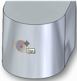
You can place a dimension using the intersection point at the center of a cylinder, sphere, spline, torus, or similar object.
Example:
This example shows an intersection point selected for a cylinder in a rounded face.

Instead of using two intersection points, you can place a dimension using one intersection point and another type of point, such as a keypoint.