Note:
The assembly, part, or sheet metal model must be activated in an assembly.
(Set an active dimension plane) When you select a PMI dimension or annotation command, you can use the current dimension plane or redefine it. To redefine it, choose the Lock Plane command  to Set a PMI Dimension and Annotation Plane.
Tip:
You can set a different active plane at any time during the process of annotating the model.
(Annotate the 3D model or model view) Do any or all of the following:
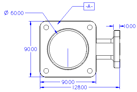
Add dimensions and annotations using any of the commands on the PMI tab on the ribbon.
In the ordered environment, use the Copy to PMI command  to select and copy 2D dimensions and annotations from a sketch or profile-based feature to the 3D model.
Use the Move Dimension command to adjust the positions of dimensions and annotations by moving them in a direction that is normal to the offset plane where they reside.
Use the Properties command on a selected PMI element shortcut menu to edit PMI text height, font, leader line, terminator, and other properties.
Use the Edit Definition command on a selected PMI element shortcut menu to edit other options used to place it, including position, alignment, and text angle.
(Create a PMI model view of the annotated model) To create a PMI model view of the current model orientation, view settings, and PMI dimensions and annotations, choose the PMI tab→Model Views group→ View command  .
.
Tip:
You can use the Keypoints option on the command bar to ensure only valid keypoints are selectable when you place a locked dimension to change the model. Choose the Center And Endpoints Only option from the list.
You can use the Midpoint option on the command bar when you must dimension a model using midpoints. Note that these midpoints are created with respect to the virtual endpoints of an edge-if applicable.
In the ordered environment, you can:
Use the Set Axis command if you want to place dimensions and annotations that are perpendicular to or parallel to an edge. You may want to use the new dimension axis, rather than the default axis, while you are placing dimensions with the Distance Between, Angle Between, Coordinate Dimension, and Symmetric Diameter commands.
Use the Dimension Axis option on the command bar to place dimensions and annotations at an angle. You may want to use the new dimension axis, rather than the default axis, while you are placing dimensions with the Distance Between, Angle Between, Coordinate Dimension, and Symmetric Diameter commands.
You can use the Lock Dimension Plane option on the command bar to change the active dimension and annotation plane from the default, implied plane of the model face.