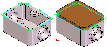
When constructing the parts and assemblies for a design project, you can use the geometry on other parts in the assembly to help you construct a new part or subassembly. For example, you can use the Include command to create 2D geometry for the base feature of a new part by copying edges on an existing part.
Depending on the approach you use, the included geometry can be associative or non-associative to the original edges.
When you create new geometry associatively, then modify the original, or parent geometry; the child geometry also updates. If you change the size of the parent part, the included child geometry for the base feature also updates.
Note:
An Inter-Part Associativity tutorial is available that demonstrates how to create associative inter-part features.
Note:
When designing in the context of an assembly, only ordered features can be linked using Inter-part relationships. In the synchronous environment faces can be copied, but they are not linked to geometry contained in the part that the face was copied from.
The following commands and functions in Solid Edge allow you to use existing geometry associatively:
Include command
Inter-Part Copy command
Assembly-Driven Part Features
Reference Plane Definition
Feature Extent Definition
Variable Table
Note:
Many of these options are available only when you set the proper inter-part associativity option on the Inter-Part tab on the Options dialog box.
When one part is associatively linked to another part in Solid Edge, special symbols are used to indicate the associative link. For example, when you include an edge from another part in the assembly to define the profile for cutout feature in the active part, a link symbol is displayed adjacent to the part feature in PathFinder and adjacent to the part entry in PathFinder.

These associative links between parts are called inter-part links to indicate that one part is dependent on another part for the definition of some of its geometry. The link information is added to the highest level assembly that is common to both parts, based on the assembly you opened.
For more information about managing inter-part links, see the Managing Inter-Parts Links section of this Help topic.
You can use the Include command to include edges from the active part, an assembly sketch, or the other parts in the assembly. When including edges from an assembly sketch or another part in the assembly, you can control whether the included edges are associative to the parent element using the Inter-Part Locate options on the Include dialog box.
You can only include elements from an assembly sketch or the other parts in an assembly when you are editing a part in the context of an assembly (you have in-place activated a part or you are creating a part in place).
When the Allow Locate of Peer Assembly Parts and Assembly Sketches option is set, you can locate and select elements in other parts and assembly sketches. To copy the elements associatively, you must also set the Maintain Associativity When Including Geometry From Other Parts in the Assembly option. When this option is cleared you can copy elements from other parts and assembly sketches non-associatively.
Note:
To include elements associatively between documents, set the Allow Inter-Part Links Using: Include Command in Part and Assembly Sketches option on the Inter-Part tab on the Options dialog box.
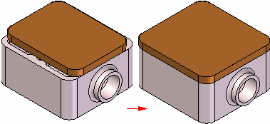
You can use the Inter-Part Copy command in the Part and Sheet Metal environments to associatively copy faces, features, and entire parts into another part document as construction geometry. You can then use the Include command to associatively copy edges from the construction geometry into a profile for a feature. To ensure that the Include command only copies edges from the associative construction geometry, turn off the assembly display using the Hide Previous Level command on the View tab.
The Inter-Part Copy command is only available when you are editing a part in the context of an assembly (you have in-place activated a part or you are creating a part in place).
Note:
To copy elements associatively between documents, set the Allow Inter-Part Links Using: Inter-Part Copy Command option on the Inter-Part tab on the Options dialog box.
You can use the assembly feature commands such as Cutout, Hole, and Revolved Cutout in the Assembly environment to construct assembly-driven part features in an assembly. You can specify which parts in the assembly you want to cut. Assembly-driven part features are added as a linked feature to each part document.
For more information on assembly-driven part features, see the Assembly-based Features Help topic.
Note:
To construct assembly-driven part features in an assembly, set the Allow Inter-Part Links Using: Assembly-Driven Part Features option on the Inter-Part tab on the Options dialog box.
When constructing a feature for a part, you can use an assembly reference plane to define the new feature. If the assembly reference plane is modified, the feature associatively updates. To select an assembly reference plane, press the SHIFT key, then select the assembly reference plane.
You can only use an assembly reference plane when you are editing a part in the context of an assembly (you have in-place activated a part or you are creating a part in place).
Note:
To use an assembly reference plane while constructing a part feature, set the Allow Inter-Part Links Using: Assembly Reference Planes In Feature option on the Inter-Part tab on the Options dialog box.
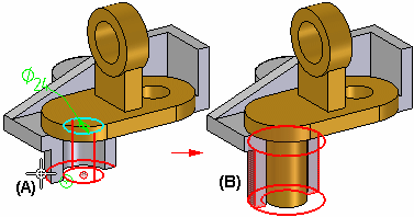
When working within the context of an assembly, many feature commands allow you to select a keypoint on another part in the assembly to define the extent for a feature. For example, when constructing a protrusion in the Part environment, you can select a keypoint (A) on another part in the assembly during the Extent Step.
The extent for the feature is associative to the keypoint on the part you select. If the other part is modified (B) such that the keypoint location changes, the extent for the linked feature also updates.
You can also use an assembly sketch to define the extent for a feature.
You can use the Variable Table in Solid Edge to associatively paste an assembly variable into a part or subassembly. This allows you to control several parts at once with one variable. For example, you can create an assembly variable to control the size of a hole in several parts in the assembly.
For more information on pasting variables between documents, see the Linking Variables Between Parts in an Assembly section of the Variables Help topic.
Note:
To associatively paste variables between documents, set the Allow Inter-Part Links Using: Paste Link To Variable Table option on the Inter-Part tab on the Options dialog box.
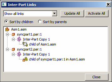
You can use the Inter-Part Links dialog box to view and manage the inter-part links you create between the parts and assemblies for a design project. You display the Inter-Parts Links dialog box using the Inter-Part Manager command on the Tools tab.
|
Legend |
|
|---|---|
|
|
Part |
|
|
Assembly |
|
|
Inter-part copy |
|
|
Variable |
|
|
Reference plane |
|
|
Sketch or Profile |
|
|
Feature Extent |
|
|
Link is intact |
|
|
Link status cannot be determined because parent is inactive |
|
|
Parent is not found |
|
|
Link to parent is broken |
|
|
Link has multiple solutions |
|
|
Link is out-of-context with its container assembly |
The Inter-Part Links dialog box allows you to sort the inter-part links by parents or by children. When set to Children, each part or assembly that is a child in an inter-part relationship is displayed. Below each child is a description of the type of inter-part relationship and the name of the parent document. When set to Parents, each part or assembly that is a parent in an inter-part relationship is listed. Below each parent is the name of each of its children.
In the Inter-Part Links dialog box, special symbols are used to indicate the status of the associative links:
 The link is intact and if design changes are made, the link should update properly.
 The status of the link cannot be determined because the parent document is currently inactive. You can resolve this with the Activate All command on the shortcut menu to activate all the parts in the assembly with associative links.
 Parent is not found. This can occur if, for example, you rename the parent file outside of Revision Manager. This can be fixed by renaming the file back to its original name.
 Link to parent is broken. This can occur if a feature that another part is dependent on is deleted. For example, a cutout feature in Part P1 is used to create an inter-part copy in Part P2. If you then delete the parent cutout feature in Part P1, a broken link symbol would be displayed adjacent to the inter-part copy listing for Part P2.
 Link has multiple solutions. The current assembly relationship or inter-part link contains multiple solutions. To correct the problem, you can adjust the assembly relationships or use Inter-Part Manager to determine which links are affected and delete those links.
 Linked document is out-of-context with its container assembly. When you create inter-part links between documents, the link information is contained in the highest level assembly that is common to both the child and parent documents, based on the assembly you opened. When you open a child document out-of-context with its container assembly, this symbol is displayed. See the Understanding In-Context Container Assembly section for more details.
This symbol does not indicate a problem, only that inter-part links in the child document may not update properly if the parent document is modified outside the context of the container assembly. You can do one of the following:
Open the assembly listed in the Tooltip, then in-place activate the child document.
Ignore the symbol.
Break the link between the child document and parent document.
When you create the first inter-part link for a part, the link information is stored in the highest level assembly possible that is common to both parts, based on the assembly you opened (using the Open dialog box or from Windows Explorer). A document can have only one in-context container assembly.
For example, you start a design session by opening assembly A2. You then in-place activate part P4. You then create a cutout feature using included geometry from part P5, which is in assembly A5. An inter-part link is created, with part P5 being the parent part, and part P4 being the child part.
Because the assembly you opened at the start of the design session was A2, A2 becomes the in-context container assembly for part P4. To create inter-part links for part P4 in the future, you must open assembly A2, then in-place activate part P4.

In a future design session, if you were to open assembly A1, the inter-part associativity options would be disabled. For example, on the Include Options dialog box, the Maintain Associativity When Including Geometry From Other Parts in the Assembly option would not be available.
You can determine the in-context container assembly for a part using the Inter-Part Manager dialog box. When you position the cursor over the inter-part link entry in the Inter-Part Manager dialog box, a Tooltip is displayed which lists the in-context container assembly for the part.
The links collection in pathfinder can be expanded to show the links in the current open document.

Right-clicking occurrences in pathfinder gives the following options:
Expand All
Collapse All
Activate All
Update All
Freeze All
Unfreeze All
Break All
Inter-part Manager
All links can be broken or froze from the top level in the links collector, or individually by right-clicking on the expanded items in the collection.
Before you make a design change to a part or assembly that is involved in an inter-part relationship, you should first use the Activate All command on the shortcut menu in the Inter-Part Links dialog box to activate the parts that contain inter-part relationships. The Activate All command only activates those parts that contain inter-parts links in the assembly.
If you want to delete any associative links between a child element and its parent, you can select the child element in the Inter-Part Links dialog box, then use the Break Links command on the shortcut menu. For example, you may want to break the associative links to a part that used to be unique to the assembly, but now will be used in other unrelated assemblies.
When you break the associative links to a part, you can still make design changes to the individual parts, but you may need to add dimensions or edit the feature to redefine the inputs for the feature. For example, if you define the extent for a feature using a keypoint on another part, then break the link later, you can still edit the extent for the feature.
After you break the associative link, you can select the feature, then use the Edit Definition option to access the Extent Step for the feature, then type a dimension value on the command bar to define a new extent for the feature.
Note:
When you define the extent for a feature associatively using a keypoint on another part, no driving dimension for the feature extent is created.
If you break the link and then edit the feature extent by typing an extent value, a driving dimension for the extent is created.


