You can create path segments and structural frames using the Frame Design application in an assembly document. Frame Design displays additional, specialized commands for creating 2D and 3D path segments, and for specifying the 3D frame component type you want to apply to the path segments. This makes it easy to construct components that use standard structural shapes, such as square tubes, angles, and channels.
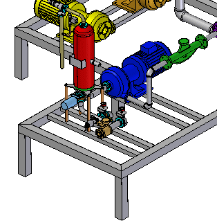
On the Tools tab→Environs group, choose the Frame Design command  .
.
Create the entire 2D framework for the 3D frame model by doing the following:
Use the commands in the Home tab→Segments group to define fully associative linear, curved, or bent segment paths for the frame cross section to follow.

Use the OrientXpres tool to add the 3D connection points to the segments.
When drawing line or arc segments, use OrientXpres to lock the orientation of the segment parallel to an axis or plane.
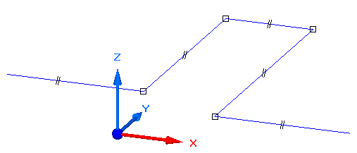
The framework can be a combination of sketches (the blue lines) and 3D line segments (the red lines). Use sketches when the frame is planar. Use edges and other geometry from 3D parts in the assembly.
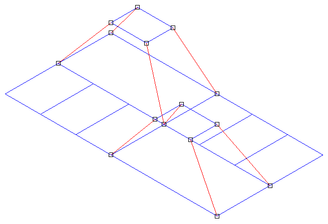
To learn how to use OrientXpres to create a 2D framework, see the Using OrientXpres activity in the Solid Edge Frame Design self-paced training course (spse01610).
Use the Home tab→Frame group→Frame command  to place frames that follow the sketch and 3D line segment paths.
The Frame command bar is displayed for you to do the following:
Choose path segments from the 2D framework.
Select cross sections to apply to those segments to create the 3D frame.
Specify corner treatment (end condition) options: Miter, Butt1, Butt2, Extend/Trim, or None.
Open the Frame Options dialog box to apply a radius, coping, and other options.
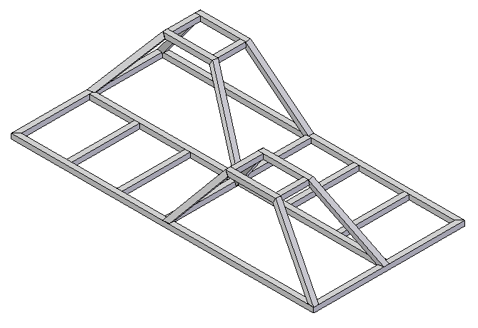
To specify the frame component type and size, you can select a cross section from the list on the command bar, or browse the standard library components.
You can add your own custom components to the library using FrameComponentsUtility.exe.
Note:
To learn how to create and use custom frame components using FrameComponentsUtility.exe, see the self-paced training module, Creating custom frame components, in the Solid Edge Frame Design course (spse01610).
The Butt1 end condition option trims against the shortest member (removes material from the longest member to suit). Butt2 trims against the longest member.
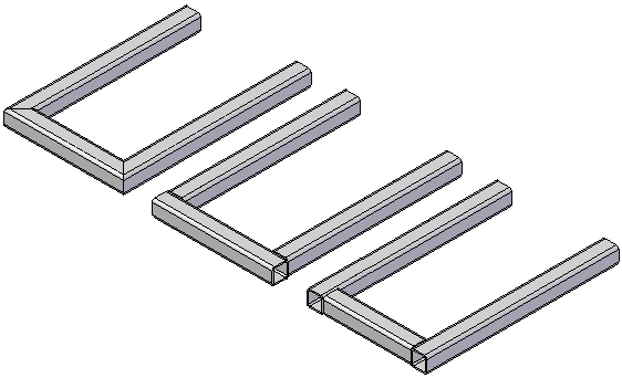
Adjust the frame component cross sections or frame end conditions for the set of components you created.
After edits are made, the system immediately recomputes the frame to show the changes.
To learn how, see the Help topics Edit a frame cross section and Edit frame end conditions.
Use the Home tab→Close group→Close Frame button to exit the structural frame design application.
See Help topic Create a drawing with the Create Drawing command to create and automatically place an isometric drawing view of the model.
To learn how, see the Help topic, Create a total length parts list. Refer to the Tips section to generate a cut length list (A) instead of a total length list.
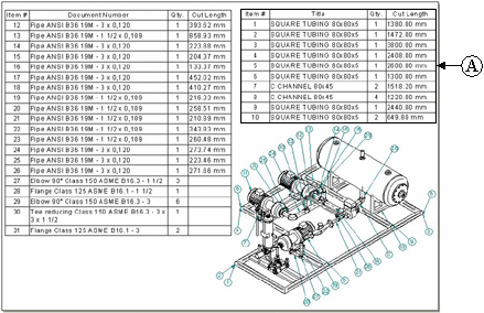
Cut length can be synchronized with Teamcenter. The value appears as a Note in Product Structure Editor.
You can use the Frame Rough-cut End Clearance option on the Options page (Parts List Properties dialog box) to specify an amount that the system automatically adds to the exact length of each frame.
You can Create a weldment assembly from your frame model, which displays weldment-specific commands. You can then add surface preparation features, define weld-bead features and weld characteristics, and add final, post-weld features.
For more information, see Help topic Weldments in assemblies.
Tip:
You can use Solid Edge Simulation to analyze a structural frame model. You can apply loading conditions to your structural frame model, and then evaluate the resulting data and plots for displacement, stress, and beam end reactions (moment, shear, axial force, and torque).