You can use the Detail View command to create an enlarged view of a specific area of an existing drawing view. You can think of a detail view as a magnifying glass focused on a special area within a drawing view.
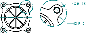
You can create circular detail views or detail views using a closed profile you draw. You can create dependent detail views that update when the source view changes, and you can create independent detail views that do not reflect changes made in the source drawing view. Similarly, independent detail views allow you to add geometry with the Draw In View command and show or hide edges with Edge Painter without affecting the source view.
Dependent detail views are tied to the source view from which they are created. To change shading, edge display, or other aspects of the dependent detail view, you must make the change in the source view and then update both views.
Independent detail views can have different display properties than the source drawing view. For example, you can show or hide parts, display hidden lines, add shading, or draw in the independent detail view without affecting the source drawing view.
Both dependent and independent views can be created from 3D geometry contained in principal views, auxiliary views, other detail views, section views, and broken out section views.
You can create a dependent detail view-but not an independent one-from a 2D Model view and from a drawing view that has been converted to 2D.
You can not create detail views from drawing views that are out of date.
Once created, you can convert a dependent detail view to an independent detail view by selecting the view then selecting the Convert to Independent Detail View command on the shortcut menu. However, you can not convert an independent detail view to a dependent view.
You define a circular detail view using the Circular Detail View option on the command bar. You can then specify the detail view envelope using three clicks of the mouse. The first click (1) defines the center of the circular area to enlarge on the source view, the second click (2) defines the diameter of the detail view circle, and the third click (3) places the detail view.
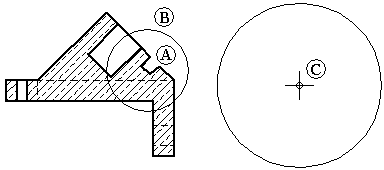
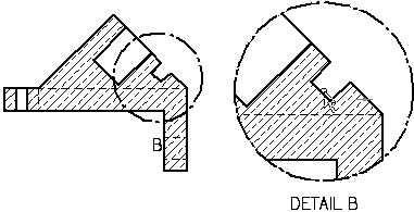
You define a user-defined shape for a detail view using Define Profile option on the command bar. You can then draw a profile the size and shape you want. Any closed profile can be a valid detail envelope.
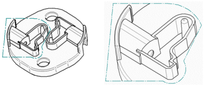
Once created, both dependent and independent views can be modified with different results. Dependent detail views are associative to the source view. When you make changes to the geometry in the dependent detail view, the source view changes. Independent detail views do not reference the source view, nor are changes made in the independent view reflected in the source view. Independent detail views can be used to show or hide parts, display hidden lines, add shading, or draw in the view without affecting the source view geometry or view properties.
To modify a dependent or independent detail view, use the Select tool and the options on the Drawing View Selection command bar to change drawing view scale, show and hide caption text, or choose a shaded or hidden line display. You also can select the Properties button to open the Drawing View Properties dialog box. The tabs that are available contain properties that you can change, which vary with detail view type.
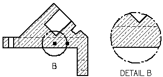
You can control caption display and formatting separately for the detail view and for the detail envelope. In addition to showing and hiding caption text using the Show Caption button on the command bar, you can change the content and formatting of a caption.
When you select a detail envelope, you can use the Caption tab (Viewing Plane, Detail Envelope, Cutting Plane Properties dialog box).
When you select a detail view, you can use the Caption tab (Drawing View Properties dialog box).
You can reposition a caption by selecting the view and then dragging the label to a new location.
The default detail envelope caption content and formatting is defined in the Drawing View style that is applied to the detail view. To learn more, see these Help topics:
If you pause the cursor over a detail view, a tooltip identifies the name of the source geometry file, the file type, and the view type. For example, the full tooltip for an independent detail view of a screw might display: High Quality View - Independent Detail View - AllenScrewM8.par. The tooltip text for a dependent detail view is simply High Quality View - Detail View - AllenScrewM8.par.
If you don't see these tooltips displayed on the drawing view, set the Show tool tips option on the Helpers tab of the Solid Edge Options dialog box.
You can hide the display of the border of the detail view after you place it. If you select the detail view border, and then select the Properties button on the command bar, you can clear the Show Detail View Border option in the Drawing View Properties dialog box.
The detail envelope drawn on the source view in the shape of a circle or user-defined profile defines the cropping boundary of the detail view. You can use the Drawing Standards tab on the Solid Edge Options dialog box to set the display standards for the detail envelope. For example, you can specify that the detail envelope display conforms to (A) ANSI, (B) ISO/DIN/JIS, or (C) ESKD standards.

You can drag a detail envelope to change its location. However, if the detail envelope is partially or fully constrained, the detail envelope will behave according to the rules of its constraints.
You can modify the detail envelope by selecting it in the original view, and then selecting Define Profile on the command bar. You can drag the detail envelope profile handles to change the size of the detail envelope. Dependent detail views on the drawing are updated when you change the size, shape, or location of the detail envelope on the source view.
If you delete the detail envelope on the source view, the detail view is also deleted.
You can use the Display Cropping Edges option on the Annotation page of the Detail View Properties dialog box to specify whether edges are displayed where the drawing view boundary intersects the model. Edges are not generated where the boundary passes over holes or voids in the model.
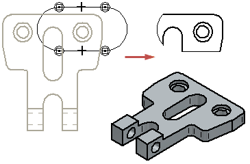
When you change this option on an existing drawing view, the drawing view becomes out of date. You can update the drawing view using the Update Views command.