 Pattern command (3D features)
Pattern command (3D features)
Pattern command (3D features)
Note:
In the Assembly environment, this command is named Pattern Assembly Feature.
Constructs a rectangular or circular pattern of selected elements. You can select part features, assembly features, edges, surfaces, or design bodies as the parent elements to pattern. For example, you can construct a hole feature, then construct a rectangular pattern of holes using the hole feature as the parent element of the pattern.
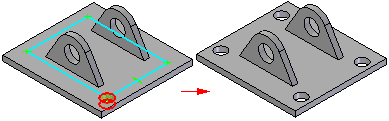
In an assembly, you can pattern assembly features, which allows you to modify two or more parts in one operation.

You can suppress individual pattern members to define gaps in a pattern to avoid other features.

Patterning elements other than features is useful when constructing models that use freeform surfaces. For example, you can construct a lofted surface, then construct a circular pattern of the lofted surface.

The basic steps for defining a pattern feature are:
Select the geometry to pattern.
Draw the pattern profile or select an existing pattern sketch.
Select the parts to be modified by the pattern (assembly documents only).
When constructing a pattern, you can also specify whether the pattern is a fast pattern or a smart pattern using the Fast and Smart options on the command bar. You can set these options at any point while creating or editing a pattern.
For more information on smart and fast patterns, see the following Help topics:
The first step in constructing a pattern is selecting the parent elements. In a part or sheet metal document, you can pattern features, edges, curves, surfaces, or the entire design body. In an assembly document, you can pattern assembly features.
Note:
When constructing and editing pattern features, you cannot have more than one element type in a single pattern. For example, you cannot pattern a hole feature, a design body, and a curve in one operation.
The Select option allows you to specify what types of elements you want to pattern. To pattern one or more surfaces or edges (model topology) that are part of a surface or solid body, you can set the Single or Chain option. To pattern one or more features, such as a cutout or protrusion, set the Feature option. To pattern a curve, surface, or solid body, set the Body option.
The name in PathFinder indicates whether you constructed a pattern using features, design bodies, or model topology (surfaces or edges).
You can select part and sheet metal features before or after starting the Pattern command. You can select the features in the graphic window or in PathFinder. You can select profile-based features or treatment features, but special rules apply when patterning a treatment feature by itself.
You can pattern treatment features by themselves or in conjunction with a profile-based feature. To pattern a treatment feature by itself, the part geometry must allow it.
When patterning other elements, such as edges, surfaces and curves, or design bodies, you must start the Pattern command, set the Select option on the command bar, then select the elements you want to pattern in the graphic window.
In the Assembly environment, you can pattern assembly features that remove material, such as holes, cutouts, and revolved cutouts. If the assembly is a weldment assembly, you can also pattern assembly features that add material, such as fillet welds, groove welds, and protrusion features.
The Select option, available during the Select Features Step, allows you to specify whether you can select material removal features, or material addition features. The Feature option allows you to select material removal features; the Body option allows you to select material addition features.
You can also specify which parts are included in the pattern feature. If you add parts to a pattern feature which were not in the parent feature, a message is displayed to instruct you the parts must also be added to the parent feature.
For more detailed information on constructing assembly-based features, see Assembly-Based Features.
Note:
You can only pattern assembly features that were created within the current assembly. You cannot pattern assembly-driven part features.
You can draw a new pattern profile or select an existing pattern profile from a sketch. If you draw a new profile, you must first specify a plane to draw it on.
Pattern profiles (A) do not have to be drawn such that they are aligned with the parent feature (B). This makes it possible to reuse pattern profiles.

When working with large or complex patterns, however, you may find it easier to construct the pattern if you draw the pattern profile so that it is aligned with the parent elements.
Note:
You can only reuse pattern profiles that were drawn as sketches.
A Pattern profile is the same as any other profile in Solid Edge. You must apply relationships and dimensions so it will behave predictably. You can also use the Variable Table to define variables between pattern profile dimensions and other dimensions on the model.
You can create rectangular and circular patterns with the Pattern command. With the profile window open, select the pattern type by clicking the Rectangular Pattern or Circular Pattern button on the Features tab. You can also draw lines, arcs, and other elements as construction geometry to help you define the pattern profile.
Note:
Any lines, arcs, and circles you draw will be automatically converted to construction geometry when you close the profile window.
You can construct rectangular patterns with the following placement options:
Fit
Fill
Fixed
With the Fit option, you specify the number of occurrences in the x and y directions, and the height and width of the pattern. The X Spacing and Y Spacing values on the command bar are calculated automatically, are read-only, and are not required to be whole numbers.
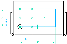
For example, you set the Fit option and then specify an X Count of 4, a Y Count of 3, a Width of 96, and a Height of 48.
The X Spacing between each occurrence is calculated automatically by dividing the Width by 3 (the X Count minus 1), for a result of 32. The Y Spacing is calculated automatically by dividing the Height by 2 (the Y Count minus 1) for a result of 24.

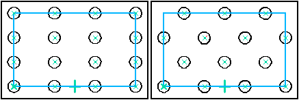
With the Fill option, you specify the x and y spacing, and the height and width of the pattern. The X Count and Y Count values on the command bar are calculated automatically, are read-only, and will always be whole numbers. The Fill option fills the area, but does not place the last row or column if the theoretical X or Y Count value is not a whole number.
For example, you set the Fill option and then specify an X spacing of 33, a Y spacing of 24, a width of 96, and a height of 48.
The X Count is calculated automatically by dividing the Width by the X Spacing, then adding 1. Since the result in this example is 3.9, which is not a whole number, there is not enough room for the fourth occurrence, so the X Count is automatically rounded down to 3.
The Y Count is calculated by dividing the Height by the Y Spacing, then adding 1. The result in this example is 3, which is a whole number, so there is room for the third occurrence.
With the Fixed option, you specify the number of occurrences in the x and y directions, and the x and y spacing. The Width and Height values on the command bar are calculated automatically, are read-only, and are not required to be whole numbers.
For example, you set the Fixed option and then specify an X Count of 4, a Y Count of 3, an X Spacing of 32, and a Y Spacing of 24.20.
The Width is calculated automatically by multiplying the X Spacing times 3 (the X Count minus 1), for a result of 96.
The Height is calculated by multiplying the Y Spacing times 2 (the Y Count minus 1), for a result of 48.40.
When you place dimensions on the pattern profile placed using the Fixed option, the dimensions are driven, since the height and width values are calculated from the values you enter for the spacing and number of occurrences.

You can construct partial or full circular patterns.

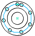
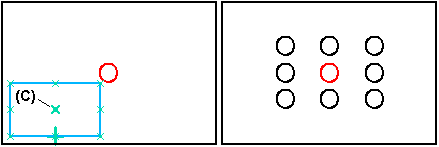
When drawing the pattern arc or circle, you specify a center point (A), a start point (B) and a direction (C).

The center point defines the center of the pattern arc or circle and also defines the axis of rotation for the feature you are patterning.
The start point defines the radius of the pattern circle. The physical size of the pattern circle has no impact on the pattern you are placing.
The direction controls whether the pattern occurrences are copied in a clockwise or counter-clockwise direction.
You can construct circular patterns with the following placement options:
Fit
Fill
Fixed
The Fit and Fill options are available with both partial and full circular patterns. The Fixed option is only available when placing partial circular patterns.
With the Fit option, you specify the number of occurrences, and the radius of the pattern circle. If you specify a partial circular pattern, you also specify the sweep angle of the arc. The angular Spacing value on the command bar is calculated automatically, is read-only, and it is not required to be a whole number.
With the Fill option, you specify the angular spacing, and the radius of the pattern circle. If you specify a partial circular pattern, you also specify the sweep angle of the arc. The Count value on the command bar is calculated automatically, is read-only, and will always be a whole number.
The Fill option fills the area, but does not place the last occurrence if the theoretical Count value is not a whole number, and the product of the angular Spacing times the Count minus 1 exceeds 360° for full circular patterns.
For example, you can create a full circular pattern with an angular Spacing of 47°, and still have a total of 8 occurrences in the pattern, since 7 times 47 equals 329. The angular spacing between the last occurrence and the parent feature will be 31°.
With the Fixed option, you specify the you the number of occurrences, the angular spacing, and the radius of the pattern circle. The Sweep value on the command bar is calculated automatically, is read-only, and it is not required to be a whole number.
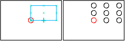
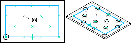
When you draw the rectangular pattern profile, the first point you click becomes the default reference point. The reference point is shown as a bold x symbol (B). Regardless of where you draw the pattern profile, the feature pattern is constructed relative to the reference point and the parent feature. For example, when patterning hole A, using reference point B, the pattern is constructed as shown.

You can change how the pattern is constructed by redefining the reference point. For example, you can move the reference point to the center occurrence (C).
By default, rectangular pattern members are aligned with each other along both axes. With the Rectangular Pattern Stagger Options dialog box you can stagger rows or columns by a given value.
To change the angle of a rectangular pattern, first delete the horizontal relationship (A) on the pattern rectangle, then place a dimension or relationship to control its angular orientation. For example, you can apply a parallel relationship (B) between the pattern rectangle and a part edge.

You can suppress pattern occurrences in rectangular and circular patterns with the Suppress Occurrence button on the command bar. With the profile window open, select the pattern profile, then click the occurrence symbols to specify which occurrences you want to suppress (A). The symbols change size and color to indicate that the corresponding occurrences are suppressed.
You can individually select occurrences to suppress, or drag the cursor to fence any number of occurrences.

This option is useful for when you need to define gaps in a large pattern, for example, to leave space for another feature.
You can also redisplay suppressed pattern occurrences with the Suppress Occurrence button. Click the button and then select the suppressed occurrences you want to redisplay.
You can also suppress a region of pattern occurrences using the Suppress Region option on the command bar. To suppress a region, you must select an existing closed sketch. The closed sketch can be of any shape. You can use the Flip option on the command bar to specify whether the suppressed occurrences are inside or outside of the closed sketch.
When constructing smart patterns, you can also delete pattern occurrences. Position the cursor over the pattern occurrence you want to delete (A), then pause. When the ellipsis is displayed, click the left mouse button to display QuickPick. You can then use QuickPick to select the pattern occurrence, then press DELETE to delete it.
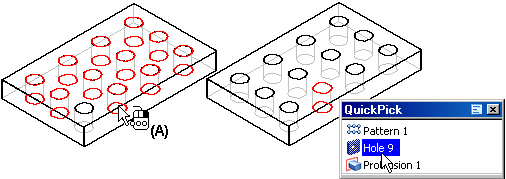
When you delete a pattern occurrence, the software is actually suppressing the corresponding x symbol on the pattern profile. Deleting, rather than suppressing, an occurrence can be useful when working with large or complex models, because you do not have to enter the profile window to suppress the occurrence. To restore the deleted occurrence, you can use the workflow for redisplaying suppressed occurrences.
You can pattern multiple elements in one operation.
When patterning features, if the Fast option fails, click the Smart option on the command bar.
You can suppress individual feature occurrences in a pattern.
You can delete individual feature occurrences in a pattern.