When sketch dimensions migrate to model edges, they become 3D PMI dimensions, which can be used to modify the synchronous model. Unless they are formula-driven, all locked dimensions unlock, so you can set individual 3D PMI dimensions to be locked or unlocked on the solid part.
In a synchronous part document, draw a sketch of the part.
Add dimensions to the sketch.
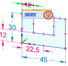
Example:
This sketch uses both locked dimensions (red) and unlocked dimensions (blue) in its construction.

Tip:
To change a dimension from locked to unlocked, click the lock symbol on the dimension value edit handle, which is displayed when you click to place the dimension.
Choose the Select command  , and then click a sketch region.
The extrude handle is displayed on the sketch.
Click either of the arrows on the extrude handle.
Example:
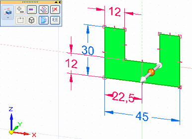
Specify the extent of the solid by doing either of the following:
Move the cursor until the extruded shape is the approximate size you want, and then click.
Define the extent precisely by typing a value in the dynamic input box near your cursor.
Example:

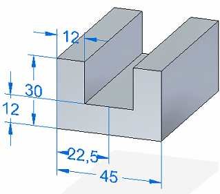
Complete the feature by clicking in free space.
All dimensions in the sketch migrated to the part and are now 3D PMI dimensions.
Example:
Tip:
You can click the dimension text in a dimension to change the size of the model face or edge.
If you want to keep a PMI dimension value from being changed indirectly, you can lock it.
Another reason to lock a PMI dimension is if you want to use it in the Variable Table.
To learn how you can use PMI dimensions to change the model, see the Help topic, Edit the model using PMI dimensions.