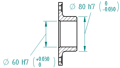
Because the tolerance specification for the proper fit between holes and shafts is such a common and critical aspect in the design and manufacture of parts, international standards bodies have established rule-based systems of tolerances for the Limits and Fits of holes and shafts.

The terms hole and shaft can also be taken as referring to the space between two parallel faces of any part, such as the width of a slot, the thickness of a key, etc. Only distance dimensions are covered by the standards. The standards do not apply to angular dimensions.
Solid Edge provides ASCII text files that you can use to automatically define the limit or fit for a dimension whose type is set to Class using the dimension command bar.
When you set the dimension display type to Class, you can choose one of several methods to display the limits or fits for the dimension.
|
Fit |
|
|
Fit, tolerance only |
|
|
Fit with tolerance |
|
|
Fit with limits |
|
|
Fit Hole/Shaft only |
|
|
Fit Hole/Shaft, tolerance only |
|
|
Fit Hole/Shaft with tolerance |
|
|
User-defined (Any user-defined text is valid) |
|
You can specify formatting options for tolerance dimensions and for class fit dimensions by editing the dimension properties or by defining it in the dimension style. Refer to the following options on the Text tab, in the Tolerance Text group:
Hole/Shaft
Three separator types are available to specify the layout of class fit hole/shaft dimensions with tolerance.
|
Use these options |
To get this layout |
|
Separator |
Vertical
|
|
Space |
Vertical
|
|
Slash |
Horizontal
|
Position
|
Use these options |
To get this layout |
|
Bottom |
Tolerance aligned to the bottom of the dimension text.
|
|
Center |
Tolerance center-aligned with the dimension text.
|
|
Top |
Tolerance aligned to the top of the dimension text.
|
Align to
The following options are available to specify alignment of the upper tolerance value with the lower tolerance value:
Decimal Point
Sign
Use tolerance text size for combined tolerance text values
When upper and lower tolerance values are the same, specifies that the combined values are displayed using the tolerance text size entered in the Size box.
Example:

Three ASCII text files are available that provide support for ANSI and ISO class fit dimension standards:
SE-LimitsAndFitsTableANSIinch.txt
SE-LimitsAndFitsTableANSIMetric.txt
SE-LimitsAndFitsTableISO.txt
By default, the files are located in the Solid Edge Preferences folder. You can instruct Solid Edge to look for these files in a different folder, including a folder on another machine on the network using the File Locations tab on the Options dialog box.
Note:
If you edit these files, save a copy of these files before you uninstall Solid Edge.
When placing a class fit dimension that displays a tolerance, you can set an option to inhibit the display of a tolerance that has a value of zero.
The Inhibit Display of 0.0 Values for Automatic Fit Tolerances option on the Text page controls whether zero value tolerances are displayed or hidden.

You can set this option for an individual dimension using the Properties command, or you can set it for all dimensions using the Style command.