Solid Edge allows you to save documents to other file formats. You can save Solid Edge files to the following formats:
|
Environment/Command |
File Formats |
|---|---|
|
Assembly |
*.bkm, *.igs, *iges, *.sat, *.stp, *.step, *.stl, *.x_b, *.x_t, *.plmxml, *.model, *.jt, *.xgl, *.catpart, *.pdf, *.u3d |
|
Draft |
*.igs, *.iges, *.dgn, *.dwg, *.dxf, *.pdf |
|
Part |
*.igs, *iges, *.sat, *.stp, *.step, *.stl, *.x_b, *.x_t, *.plmxml, *.model, *.jt, *.xgl, *.catpart, *.pdf, *.u3d |
|
Sheet Metal |
*.igs, *iges, *.sat, *.stp, *.step, *.stl, *.x_b, *.x_t, *.plmxml, *.model, *.jt, *.xgl, *.catpart, *.pdf, *.u3d |
|
Save as Flat |
*.dxf, *.par, *.psm |
|
Save as Image |
*.bmp, *.jpg, *.tif |
|
Save as Movie |
*.avi |
The Save As Translated command allows you to save an assembly file as a Unigraphics bookmark (.bkm) file. The bookmark file provides a simplified definition of the Solid Edge assembly structure that can be read by Unigraphics.
When you export a single part file from Solid Edge to PLMXML, two files are created. One of the files ends with an .plmxml extension and the other ends with an .x_t extension. The .plmxml file is an ASCII file that references the .x_t file.
When you export an assembly from Solid Edge, a file with a .plmxml extension is generated, along with a .x_t file for each unique part. In this case the .plmxml file references each body through the .x_t files and provides the correct transform. In an assembly that contains three unique parts you will have three Parasolid .x_t files.
You can save Solid Edge Assembly, Part, and Sheet Metal documents in STEP (.stp) format with the Save As command. On the Save As dialog box, after you select the Solid Edge document you want to save, click the Options button to display the Export Options for STEP (.stp) dialog box. You can use the dialog box to control how the Solid Edge document is saved in .stp format.
The Step3d.ini file, found in the Solid Edge Program folder, is used to store the settings selected from the user interface. When you change a parameter in the options form, a new value is saved to the file.
The Mapped Item Assembly= parameter is not exposed through the user interface. This parameter specified that you want to export the Solid Edge assembly as a mapped item to STEP. By default, the value is On, which saves the assembly as a mapped item. However, some modelers such as CATIA V4 or V5 are unable to read assembly written using the mapped_item format. To save the Solid Edge assembly to Catia, set the Mapped Item Assembly= parameter Off.
You can use a text editor, such as Notepad, to set these parameters. However, if you edit this file, use extreme caution in setting these parameters. Errors in this file can adversely affect translation quality.
To use the batch translator to translate a list of files, create a text file that includes the full file path for each file name you want to export. Include only one file name per line as shown in the following example.
Example: c:\My SE files/part1.par c:\my se files\asm1.asm. |
Use this text file as input to the translator.
You can use the AutoCAD Translation Wizard to save Solid Edge documents to AutoCAD format. The wizard maps entities, such as line type, line width, font, and hatch style, in a Solid Edge document to an AutoCAD document. If you want to save a Solid Edge Draft file to AutoCAD (.dxf or .dwg) format and the file contains OLE objects such as a Word or .bmp document, you must save the file first. If you do not save the draft file, the OLE objects will not be translated to AutoCAD format.
You can save Solid Edge assembly, weldment, part, sheet metal, and draft documents in the Adobe Acrobat Portable Document (.pdf) format with the Save As command. You can also save Solid Edge assembly, assembly weldment, part, and sheet metal documents to 3D Adobe Acrobat Portable Document (.pdf) or Universal (.u3d) format.
Note:
Weldment (.pwd) format is not supported.
The Solid Edge document title, author, subject, and keyword properties are copied to the new PDF document.
Assembly, part, and sheet metal documents are saved as a *.pdf file with one page. The active model view is the view saved to PDF.
Draft documents typically contain multiple drawing sheets and a 2D Model sheet. The sheet-type that is active when you use the Save As command determines what is saved to the *.pdf file. You can use the Options button on the Save As dialog box to open the PDF Export Options dialog box, where you can specify which sheets you want to save in the file, as well as to select other options.
The active model view is the view saved to PDF. All other standard views defined in View Manager, including user-defined views, are also saved.
Colors defined in the Solid Edge document are saved to the PDF document.
PMI dimensions and annotations defined in the Solid Edge document are saved to the PDF document.
The Solid Edge document title, author, subject, and keyword properties are copied to the new PDF document.
The assembly components can be displayed and hidden in the model tree of the PDF viewer.
Note:
Sketch elements are not saved to the 3D PDF file.
To learn how, see Save a document to Adobe PDF.
A Solid Edge Velocity PS Printer 2.0 printer driver is installed automatically with Solid Edge and is used by the Save As command to generate an Adobe PDF document. The default settings are sufficient for this purpose. To adjust the default PDF output properties, see the Help topic, Change PDF printer properties.
You can use the Export Multiline Text As Multiline Text parameter in the seacad.ini to control how Solid Edge exports multiline text. By default, the parameter is set to 1, which exports multiline text boxes as multiline text box. You can set the value to 0 if you want to export the text boxes as single line text boxes.
Because of differences in CAD systems and the large number of possible dimension styles that can be created, you can easily create a dimension in one system that cannot be displayed in another. The Export Solid Edge Dimensions as AutoCAD Dimensions and the Export Dimension Picture Data options on the AutoCAD Translation Wizard help you to avoid these problems and create dimensions that appear the same in Solid Edge and AutoCAD.
An AutoCAD dimension consists on three parts:
Dimension block or picture data
Dimension object
Dimension style object
The dimension block or picture data contains lines, arcs, and points that make up the dimension. The dimension object contains information about the dimension attributes, such as layer, color, definition points, and pointers to the dimension block data and dimension style object. The dimension style object contains various dimensioning variables such as tolerances, formats, and unit type.
When you open a drawing in AutoCAD, the dimension block, or picture data is displayed. If you change the dimension in AutoCAD, the picture data is deleted. AutoCAD regenerates the display based on the dimension object and the dimension style object. This may cause the dimension in AutoCAD to change based on the style and dimension limitations between the two CAD systems. You can use the Export Dimension Picture Data option on the AutoCAD Translation Wizard to avoid this problem and maintain the appearance of a Solid Edge dimension as long as the dimension is not regenerated in AutoCAD.
If you export a Solid Edge document with the Export Dimension Picture Data option on the AutoCAD Translation Wizard enabled, Solid Edge writes the block or picture data to the AutoCAD document. When you open the AutoCAD document, the dimensions will appear as they would in Solid Edge.
If you export a Solid Edge document with the Export Dimension Picture Data option on the AutoCAD Translation Wizard disabled, Solid Edge does not write the block or picture data to the AutoCAD document. When you open the AutoCAD document, AutoCAD generates its own picture data to create an AutoCAD-like dimension.
Note:
If you are exporting to .dxf format, but do not intend to open and save these documents in AutoCAD, you should enable the Export Dimension Picture Data option. If the target system is dependent on any of the block or picture data, it cannot successfully read and display the dimension correctly if the picture data is not exported. The target CAD system must be able to generate the dimension based only on the dimension object and dimension style information.
If you export a Solid Edge document with the Export Dimension Picture Data option disabled and force AutoCAD to regenerate the picture data, you may see differences in:
Radial or diameter dimensions
Limited dimensions
Prefixes and suffixes
Alternate units
In Solid Edge you can create radial or diameter dimensions and specify that the diameter symbol be displayed before the diameter value, after the diameter value, or not all. AutoCAD only allows you to display the diameter or radial symbol before the value. When you export Solid Edge dimensions as AutoCAD dimensions the diameter symbol will always be displayed preceding the diameter value.
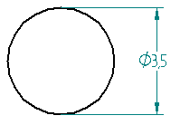
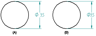
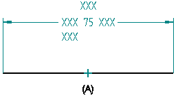
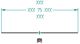
Solid Edge creates a space (A) between the dimension value and the dimension symbol to make it easier to read. AutoCAD does not support this and removes the space (B) between the dimension value and the dimension symbol when you export the Solid Edge document.
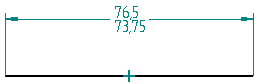
Solid Edge allows you to create a horizontal limit dimension (A) and a vertical limit dimension (B).
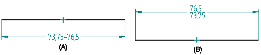
AutoCAD supports only horizontal limit dimensions. When you export Solid Edge dimensions as AutoCAD dimensions, the vertical limit dimensions will appear as horizontal limit dimensions in the AutoCAD document.
When you export dimensions as dimension objects superfixes, prefixes, suffixes, and subfixes are written as text overrides. In Solid Edge, you can set a left or centered justification when placing a subfix on a dimension. However, AutoCAD only supports a centered justification for text overrides. Therefore all dimensions created in Solid Edge with a subfix that has a left justification (A) are exported to AutoCAD as a text override, and will have a centered justification (B).
Solid Edge allows alternate units that can be ( ), Null, or [ ]. AutoCAD only supports [ ], so all alternate units in Solid Edge will be displayed a [ ] in AutoCAD.
There are a few exceptions when you export Solid Edge dimensions as AutoCAD dimensions:
Coordinate dimensions
Inspection dimensions
Dimensions with jogs
Coordinate dimensions in Solid Edge are not written as dimension objects in AutoCAD, regardless of the setting of the Export Solid Edge Dimensions as AutoCAD Dimensions option. Instead, coordinate dimensions are output as simple lines and text to represent the dimensions, just as if the Export Solid Edge Dimensions as AutoCAD Dimensions option was disabled.
You can create inspection dimensions in Solid Edge, but AutoCAD does not support them. When you export a Solid Edge document, all dimensions that have an inspection block are exported as a dimension and an oval inspection block is created from graphics, and both are placed as an AutoCAD block element.
Any dimension with a jog is exported as simple lines and text to represent the dimension just as if the Export Solid Edge dimensions as AutoCAD Dimension control was disabled.