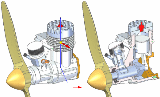
A 3D section view:
Simulates cutting away material from the model so you can see internal features. This is useful when you need to create sectioned views of a part or assembly for presentation or documentation purposes, but you do not want to physically modify the parts.
Is created using the Section command in the Assembly, Part, and Sheet Metal environments.
Can be annotated, measured, and used to provide documentation for Product Manufacturing Information (PMI) purposes using the commands on the PMI tab. When you change any of the driving dimensions that control the model, the PMI dimensions update, also.
Can be used to generate drawings automatically.
Can be saved as a presentation-quality image when you use the Save As Image command.
When the synchronous model is displayed, before you select the Section command you must first use the drawing commands on the Sketching tab to define the cutting plane shape. See Defining 3D sections of models: best practices.
Then when you start the Section command, the Section View command bar guides you through the steps:
Select Sketch Step: Select the previously created 2D elements to define the cutting plane.
Optional: Use the Section Options dialog box to edit or confirm the default settings for section caption, dimension style, and cutting plane annotation.
Side Step: Define the side of the model or profile you want to remove material from.
Extent Step: Define the thickness of the material you want to remove.
Select Parts Step: Choose to cut all the parts in the model, cut only the selected parts, or cut only the unselected parts.
In assemblies, you do not have to cut every part that the section view profile passes through.
In the Select Parts Step, you can use the Cut List option on the command bar to specify which parts to cut.
After you specify the parts you want to cut, use the Preview button to observe the results.
You can create multiple section views of a part or assembly.
With the ordered model displayed, the Section command prompts you to select a plane or model face to draw on, and then displays the 2D drawing tools for you to draw a 2D profile to define the cutting plane shape. See Defining 3D sections of models: best practices.
When you click Close Sketch, the remaining steps on the Section View command bar are the same as for synchronous environments.
According to industry standards, hardware parts such as bolts, nuts, and washers are not cut in section views.
In general, parts can be marked as 'hardware' by selecting the Hardware Part check box on the Project page of the File Properties dialog box.
When defining or modifying the section view, you can use the Cut Hardware option on the Section Options dialog box to specify that hardware is cut in that view.
See the help topic, Specify hardware parts.
Existing 3D section views are listed on, and controlled from, PathFinder. To modify a section view, you must select it on PathFinder.
To display a section view, click the box next to the section view name on PathFinder.
To display more than one section view at a time, click the boxes next to the additional section view names.
To modify an existing section view, use the section shortcut commands available from Feature PathFinder. Right-click the section view name you want to modify, and then select the appropriate edit command on its shortcut menu. For example, you can:
In the ordered environment, modify the section profile using the Edit Profile command.
In the synchronous environment, modify the section using the Edit Definition command.
Choose different cut parts using the Options command.
For viewing purposes, you can add a 3D section view to a selected 3D model view using the Add To Model View command on the section view shortcut menu.
See the Help topic, Add section views to a 3D model view, for more information.
You can print a 3D section view of the model displayed in the graphics window using the Print command on the Applications menu. If the section annotation is displayed in the view, then the cutting plane direction arrows are printed with the section view.
Note:
If the section is rendered in Visible and Hidden Edges mode in the part, sheet metal, or assembly document, then you must also set the Print As Displayed option on the Print dialog box to print the view in this format.
You can place a 3D section view in a drawing by choosing the New→Create Drawing command from the Application menu in the model document. After placing a drawing view of the model on a drawing sheet, you can expose the 3D section view you created. To learn how to do this, see Expose a 3D section in a drawing.