The Text and Leader tab in the properties dialog box contains options that specify how annotations such as leaders, balloons, callouts, control frames, and symbols are displayed. Not all options are available for all annotations.
Text
Specifies how the text appears in an annotation. Changes in these fields override the default text style.
Font
Specifies the font to use for the text.
Font style
Specifies the font style to use for the text.
Font Size
Specifies the text size of 2D annotations.
In synchronous models, this option also specifies the text size of PMI annotations.
Fill text with background color
Fills the text with the current background color.
Leader & Projection Line
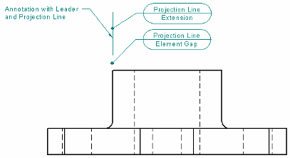
Specifies how a leader or projection line is displayed. The Element Gap and Extension settings are applied when the annotation is moved beyond the edge of the annotated element they are attached to, as illustrated here.

Break line
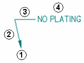
Shows or hides a horizontal break line (3) where the leader line (1)(2) meets the annotation (4), as illustrated here.

The length of the break line is specified as a multiple of the font size, for example, 1.5 x Font Size.
Break line angle
Sets the break line angle with respect to the Break Line Position option specified on the Leader command bar.
When the Break Line Position is horizontal or vertical, the angle is set to 0.00 degrees automatically. When you change the Break line angle value, the break line is rotated from that horizontal or vertical starting position. You can use positive or negative numbers to rotate the break line in a counterclockwise or clockwise direction, respectively.
Note:
You also can use the Angle box on the Leader command bar to specify the break line angle.
Element gap
Specifies how far the projection line is set back from the annotated element. This value is a multiple of the font size.
Extension
Specifies how far the projection line extends beyond where the leader attaches to the projection line. This value is a multiple of the font size.
Color
Sets the color of an annotation.
Line width
Sets the width of annotation lines, such as leader lines, break lines, and reference lines.
Angle
Specifies the orientation angle for text in an annotation. This option is not displayed for leaders.
Symbol line width
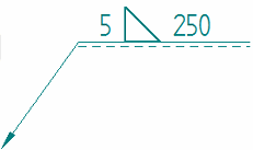
Specifies the line width used in weld symbols.
Example:

To apply the Symbol line width to PMI weld symbols, you must also select the PMI tab→Dimension group→Model Size PMI command on the ribbon.
Note:
You can use the Line width option on the Text and Leader tab to specify a different width for the leader, reference, and tail lines associated with the weld symbol.
Text scale
Applies a scale value to the text height of annotations. Increasing or decreasing the text scale changes the overall text size. The default is 1.0.
Aspect ratio
For callout text and symbols, specifies the font width with respect to height. Increasing or decreasing the aspect ratio only changes the font width of the selected callout; the height is unchanged.
Example:

Terminator
Specifies how the terminator is displayed on the leader.
Type
Sets the terminator type.
|
Datum frame terminator type |
Displays |
|
Anchor (filled) |
|
|
Anchor (hollow) |
|
|
Line |
|
|
Normal |
Uses the active terminator type for dimensions, for example:
|
|
Datum target terminator type |
Displays |
|
Arrow (filled) |
|
|
Arrow (hollow) |
|
|
Arrow (open) |
|
|
Blank |
No symbol is displayed on the terminator line. |
Length
Sets the length of the terminator. This value is a ratio of the font size.
Terminator line width
Specifies the terminator line width when the terminator type is set to Line.
The default width is the Datum frame terminator line width on the Terminator and Symbol tab in the Dimension Style dialog box.
All around symbol size
Specifies the diameter of the all around symbol. This value is a ratio of the font size. The default is 1.0.