Use the Smart Dimension command  to places a dimension on any single element, between any two elements, or between elements in different drawing views of the same model. The dimension types that are available with the Smart Dimension command depend on the elements you select.
When placing dimensions between drawing views, the views must share the same view plane. For example, you can add a dimension between an edge in a front view and an edge in a detail view with the same front orientation, but not between a front view and a side view.
You can use Smart Dimension to place a dimension on the following single elements:
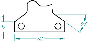
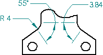
Length and angle of a line
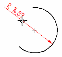
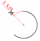
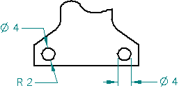
Radius and diameter of a circle
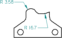
Length, angle, radius, and diameter of an arc
Radius of an ellipse or curve
You can also use Smart Dimension to place a dimension between any two elements, such as:
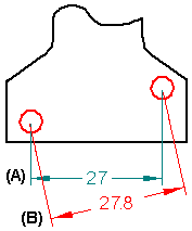
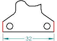
Between two linear elements
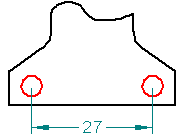
Between two circular elements
Before you click to place the dimension, you can use the following keys to affect the dimension that is created. The options that are available depend upon what, and how many, elements you select. Refer to the specific prompts displayed on PromptBar as you select elements.
|
Keyboard options |
Result |
|
A |
Changes between a linear dimension and an angular dimension. |
|
B |
For PMI, changes the dimension orientation back to the previous dimension plane in sequence. |
|
D |
Changes between a radial dimension and a diameter dimension. |
|
I |
For PMI, selects an intersection point. |
|
N |
For PMI, changes the dimension orientation to the next dimension plane in sequence. |
|
Shift |
Alternates between:
|
|
Alt |
For a radial or diameter dimension, adds a projection line extension to the dimension.
|
|
Q |
Turns automatic locate off and on so you can select a different element to dimension to. |
Place a class fit dimension by first selecting Class from the Dimension Type list, and then selecting the class fit dimension type from the Type list.
Specify additional dimension text or symbols by selecting the Prefix button to open the Dimension Prefix dialog box.
Adjust the round-off of all dimensions and tolerance values by selecting the Advanced Round-off button to open the Round-off dialog box.
You can use the Properties command to open the Dimension Properties dialog box to specify other aspects of dimension formatting. For example, you can specify the length and size of dimension lines and projection lines (on the Lines and Coordinate tab), and the gap between the dimension text and the dimension line (on the Spacing tab).
You can use Alt+click to add one or more jogs to a selected horizontal or vertical dimension projection line.
![]()
You can drag the segment or the handle points created by the jog to change the length and orientation of the jog lines.
You can remove a single jog on an existing dimension by selecting the projection line and then holding the Alt key while you click the jog key point. You can remove all of the jogs on a selected projection line using the Jog button on the command bar.
For more information, see Add and remove jogs on a dimension.
Place a locked dimension on a drawing