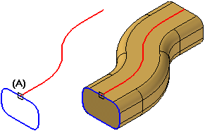
The ability to define paths and cross sections using sketches is especially useful when working with swept features and lofted features. Drawing sketches first allows you to draw the wireframe geometry without constructing the feature. Since a sketch profile is not validated when you close the sketch window, you can also save your work before you complete the design. This approach also allows you to experiment with both swept and lofted features using the same sketch geometry.
You can also define relationships between sketches on different planes. For example, you may need to use connect relationships (A) between path and cross section keypoints. You cannot define relationships in this manner if you draw the profiles within the swept feature commands.

You can also use the Include command to include part edges into a profile or sketch, then use the profile or sketch in a swept feature.
You can use edges of existing surface and solid geometry to define path curves or cross sections. You can also use derived elements, such as intersection curves, contour curves, cross curves, wrapped curves, and so forth to define path curves or cross sections.