Saved Settings
Lists the saved callout settings.
Save
Saves the specified callout settings to the name entered in the Saved Settings box.
Delete
Deletes the selected saved callout setting.
Callout Text
Enter the primary callout text in this box. Information can be typed, copied/pasted, property text, or special characters. Press the Enter key to start a new line of text. The position of the cursor determines where the text displays in the callout.
Callout Text 2
Enter the secondary callout text in this box. Information can be typed, copied/pasted, property text, or special characters. Press the Enter key to start a new line of text.
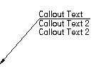
The secondary text displays below the primary callout text. If the primary callout text is above the callout line, then the secondary text will display below the line. For example:
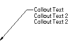
If the primary callout text is embedded in the callout line, then the secondary callout text will display directly below it. For example:
Special Characters
Adds special font characters, such as diameter, counterbore, or depth, to the callout text. Pause the cursor over a symbol to see what it represents.
Hole Reference
Adds a thread reference, such as thread size or thread depth, to the dimension or callout text. Thread references are associative to the part feature they refer to and will update if the thread characteristics of the feature are modified. To reference straight and tapered thread information, refer to the file named PipeThreads.txt in the Solid Edge/program folder. Thread size, thread depth, and smart thread depth is used for both straight and tapered threads.
Smart Depth
References the hole depth data from the Smart Depth tab of the Modify Dimension Style dialog box.
Bend
References bend information for flattened sheet metal drawing views. For example:
 Included Angle—Displays the inside bend angle (A).
 Angle—Displays the outside bend angle (B).
 Property text
Selects property text to be displayed in parts lists, balloons, callouts, and other annotations. To learn how you can use property text, see Using property text.
For a complete list of property text and format codes, see these help topics:
Taper Symbol
Displays the taper symbol on the break line when these conditions are met:
The Taper Symbol option is set to Left or Right to define the direction you want it to point.
On the Callout command bar, the text Position option is set to Above the line  .
.
Hole Callout
References the hole callout data from the Hole Callout tab of the Callout Properties dialog box or the Hole Callout tab of the Modify Dimension Style dialog box.
![]() Select Symbols and Values
Select Symbols and Values
Opens the Select Symbols and Values dialog box for you to generate the appropriate symbols and model-derived values without having to type the property text codes yourself. Examples of the types of symbols you can select include ± (plus minus), ° (degree), and ∅ (diameter). Examples of model-derived values include hole references, bend data, and weld beads.
All around symbol with leader
Displays the all around symbol with a leader line on the callout.
You can change the symbol size using the All-around symbol size edit box on the Text and Leader page.
All over symbol with leader
Displays the all over symbol with a leader line on the callout. This option is not available when the All around symbol with leader check box is selected.
You can change the symbol size using the All-around symbol size edit box on the Text and Leader page.
Show this dialog when the command begins
When set, displays the Callout Properties dialog box automatically when you select the Callout command. When cleared, you have to use the Properties button on the command bar to open this dialog box.
The default is to show the dialog box.
Preview
Shows you the result of your settings before you apply them.